
75. I2C Slave with Sleep Mode
From the task, we understand that,
- Low-power operation: The slave stays in a low-power state, waking up only when the TWI address matches.
- Minimal power consumption: Ensures the slave consumes very little power during idle periods.
- Power-down Sleep Mode: Utilizes the highest power savings available on the ATmega328P (Arduino UNO).
- User interaction: The slave wakes up and reads the ADC value response back to the master only when the user presses the button connected to the master.
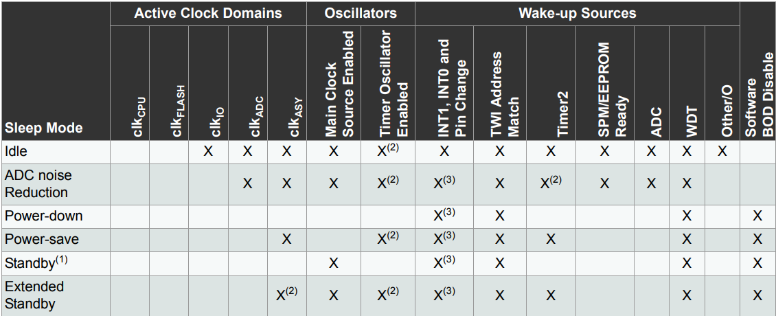
The Arduino UNO (ATmega328P) supports six sleep modes, each offering different power-saving levels:
- IDLE Mode – Lowest power saving, CPU stops but peripherals (Timer, ADC, Serial, etc.) keep running. Fast wake-up.
- ADC Noise Reduction Mode – Reduces noise for ADC conversions by stopping the CPU and some peripherals.
- Power-down Mode – Maximum power saving; Only an external reset, watchdog reset/interrupt, brown-out reset, 2-wire serial interface match, INT0/INT1 level interrupt, or pin change interrupt can wake the MCU. All generated clocks halt, except for asynchronous modules.
- Power-save Mode – Similar to Power-down but allows Timer2 to keep running for periodic wake-ups.
- Standby Mode – Like Power-down, but with an active oscillator for faster wake-up.
- Extended Standby Mode – Same as Standby, but keeps Timer2 running for periodic tasks.
For best power efficiency, use Power-down Mode with TWI address match interrupt for wake-up.
Here is a comparison of all sleep modes available in the Arduino UNO (ATmega328P):
Hardware connection
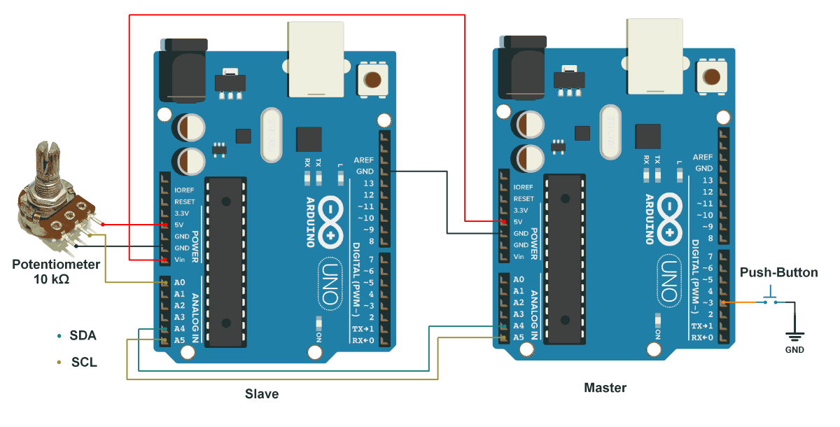
Slave:
- Power connections :
- VCC (5V master’s pin) → slave's VIN pin.
- GND → GND (common ground).
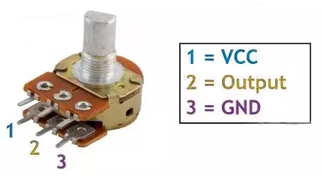
- Potentiometer:
- Terminal 1 → VCC.
- Terminal 2 → Pin A0.
- Terminal 3 → GND.
Master
- Connect the Master (Arduino UNO) board to the PC using a USB cable to establish communication with the Serial Monitor.
NOTE: USB also provides power to both boards.
- Push Button:
- Terminal 1 (NC terminal) → pin D3 of Master (with an internal pull-up resistor).
- Terminal 2 (NO terminal) → GND.
Circuit Connection
Firmware
- Low-power I2C slave: Slave Arduino operates in power-down mode to save energy. During sleep mode, Arduino’s I2C module stays active. When an I2C address match occurs it generates TWI address match Interrupt.
- Wake-up on I2C request: TWI address match Interrupt triggers the slave to wake up when the master requests data.
- ADC reading: Reads an analog value from a potentiometer, on pin A0.
- Data transmission: Sends the read 10-bit ADC value to the I2C master.
- Return to sleep: After responding, the Arduino goes back to sleep to minimize power consumption. During sleep mode, Arduino’s I2C module will stay active.
Code
#include <avr/sleep.h>
#include <avr/power.h>
#include <avr/wdt.h>  // Include WDT library
#include <Wire.h>     // Include the Wire library for TWI/I2C communication

#define ADC_PIN A0        // ADC Input Pin
#define TWI_ADDRESS 0x08  // Set the TWI (I2C) address

volatile bool isRequest = false;

void wakeUpISR() {
  // Empty ISR, just needed to wake the microcontroller on address match interrupt
}

void setup() {
  pinMode(13, OUTPUT);
  digitalWrite(13, LOW);  // Turn off the onboard LED for power saving

  // Disable Watchdog Timer
  cli();                               // Disable global interrupts
  wdt_reset();                         // Reset WDT
  MCUSR &= ~(1 << WDRF);               // Clear WDT reset flag
  WDTCSR |= (1 << WDCE) | (1 << WDE);  // Enable WDT configuration mode
  WDTCSR = 0x00;                       // Disable WDT
  sei();                               // Enable global interrupts

  // Disable External Interrupts (INT0 and INT1)
  EIMSK = 0;

  // Start the TWI (I2C) communication and set the address
  Wire.begin(TWI_ADDRESS);
  Wire.onRequest(requestEvent);  // Register the request handler for address match
  power_twi_enable();            // Enable TWI
}

void enterSleepMode() {
  set_sleep_mode(SLEEP_MODE_PWR_DOWN);  // Set sleep mode
  cli();                                // Disable interrupts to avoid race conditions
  sleep_enable();
  sleep_bod_disable();  // Disable Brown-Out Detector for lower power
  sei();                // Re-enable interrupts
  sleep_mode();         // Enter sleep mode (Execution stops here)

  // Code resumes here after wake-up
  sleep_disable();
  delay(10);  // Wait a short time for stability
}

void requestEvent() {
  // Respond to the master's request for data (ADC value)
  uint16_t adcValue = analogRead(ADC_PIN);  // Read ADC value
  Wire.write(adcValue & 0xFF);              // Send lower nibble
  Wire.write((adcValue >> 8) & 0xFF);       // Send higher nibble
}

void loop() {
  enterSleepMode();  // Sleep until an address match occurs
  // The requestEvent() function will be triggered automatically when address match occurs
}
Code Explanation
This Arduino I2C slave program minimizes power consumption by entering power-down sleep mode and waking up only when an I2C master requests data.
NOTE: During sleep mode, the TWI module stays active. When the TWI address match event occurs, it wakes up the Slave from sleep mode.
Key Functionalities:
- Setup:
- Turn off the onboard LED to save power.
- Initializes I2C slave communication with address
0x08. - Registers
requestEvent()to handle data requests. - Disable the WDT and External Interrupts (INT0 and INT1) for extra power saving.
- Sleep Mode (
enterSleepMode):- Configures power-down sleep mode to conserve energy.
- Disables the Brown-Out Detector (BOD) for extra power saving.
- The microcontroller sleeps until an I2C request triggers a wake-up.
- Handling I2C Requests (
requestEvent):- Reads the ADC value from pin
A0. - Sends the 16-bit ADC value in two bytes via I2C.
- Reads the ADC value from pin
- Loop:
- Puts back the Arduino to sleep until an I2C master sends a request.
Working Flow:
- The Arduino sleeps to save power.
- When an I2C master requests data(transmits a slave's address), the slave wakes up automatically.
- It reads the ADC value and sends it over to I2C.
- After responding, it goes back to sleep to minimize power usage.
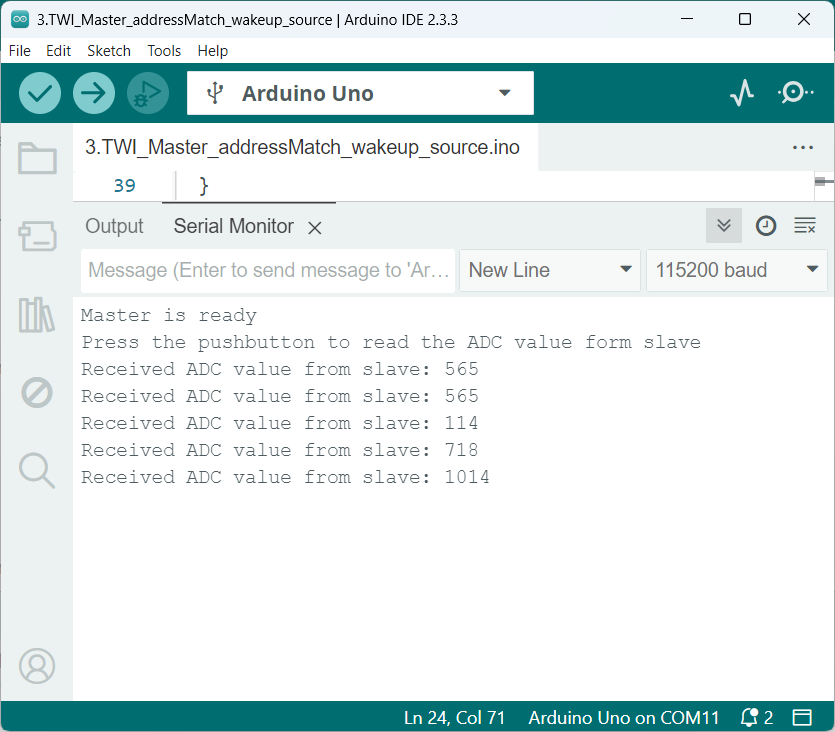
Output
Power Saving Analysis
- Active Mode Consumption: 25-30 mA.
- Sleep Mode Consumption: 14-17 mA.
- Power Reduction: Significant decrease in the current draw by enabling sleep mode.
- Conclusion: Implementing sleep mode enhances energy efficiency.
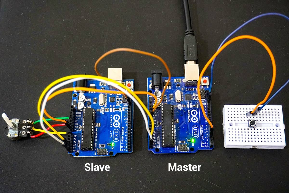
Hardware Setup
Serial Monitor Master Output
Video