32. Smart OhmMeter
We can use a voltage divider method to calculate the resistor value.
We can put a known resistor (R1) in the voltage divider and measure the divided voltage using ADC.
Since we know all other parameters i.e. R1, VCC, VR2 (divided voltage), by using simple formulas, we can calculate the unknown Resistor R2.
Unknown Resistor calculation using voltage divider
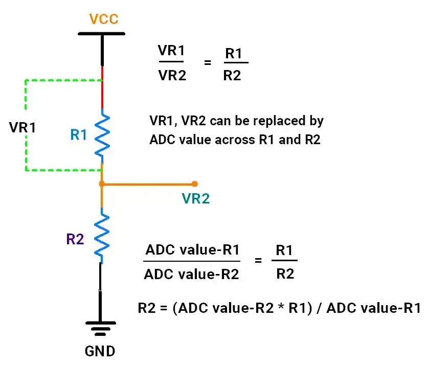
Calculating resistance
ADC_value_R1 can be calculated as 1024 - ADC_value_R2
R2 = (ADC_value_R2 * R1) / (1024 - ADC_value_R2)
However, if the known resistor connected is 100Ω and we have to measure 100KΩ, which is quite unproportionate and will give us less accuracy.
So we need to use a resistor R1 closer to 100KΩ for better accuracy.
So to measure resistor values for a range of 10Ω to 500KΩ, we need to use various values of known resistors for better accuracy.
We can connect them to separate ADC channels where the ADC pin will also act as a source (VCC).
There is an important reason for connecting all known resistors to ADC channels rather than general GPIO pins. We will get back to that.
Let’s use 4 different resistors with various values.
Circuit connections
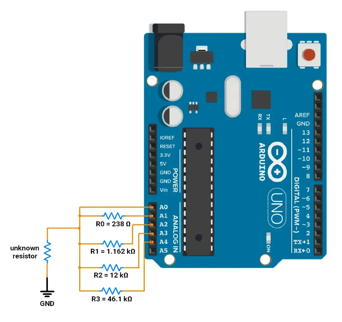
As shown in the above circuit, we can connect known resistors by turning Arduino’s ADC GPIO Output HIGH.
The rest of the resistors will be disconnected by INPUT LOW (Floating State).
A floating state means no connections to that pin, i.e. Resistor terminal is not connected to anything. So this will ensure that resistors are disconnected and do not interfere with the active resistor divider circuit.
- We have used 5 Analog pins of Arduino.
- A0 : mesure the voltage at VR2.
- A1 - A4: 4 resistors with different values.
- We used resistors with the following values
- R0 = 238 Ω
- R1 = 1.162 kΩ
- R2 = 12 kΩ
- R3 = 46.1 kΩ
So by using A0, we can measure, the ADCvalue_R2 value. We can get ADCvalue_R1 by
ADCvalue_R1 = 1023 - ADCvalue_R2
However, there is an issue. GPIO has an internal resistance of around 25Ω, which depends on various factors. When current flows through GPIO HIGH, its voltage drops based on current flows, the higher the current more the voltage drops.
Example: GPIO HIGH ideally provides 5 volts if no current is flowing. If we withdraw 10mA, approximately 250mV drop (25Ω (internal GPIO R)*10mA), giving 4.75 V on the GPIO pin.
In our case, based on known Resistor and unknown, current will flow dropping the GPIO voltage as low as 4.5 volts.
So to know this voltage drop, we can use that specific ADC channel to read its own pin voltage, i,e. Making that ADC GPIO Output HIGH, we can measure it.
So our formula will be
ADCvalue_R1 = dropped_VCC - ADCvalue_R2
where dropped_VCC is the specific ADC channel value read on the corresponding resistor’s (A1 - A4) pin.
Code Approach
NOTE: Each analog pin that is connected with the resistor will be INPUT, LOW initially. This puts it in a high-impedance state (disconnected).
When an unknown resistor is connected, the code has the following flow
- Read VR2 and VCC (Analog pin), across all resistor values.
- Detect the most accurate reading.
- Calculate the resistance of the unknown resistor & print it on a Serial monitor.
Code
#define NUM_ADC_CHANNELS 4  // number of ADC channels used

uint16_t ADC_values_vr2[NUM_ADC_CHANNELS] = { 0, 0, 0, 0 };                      // ADC values of volatage measured across r2 i.e. VR2
uint16_t known_resistor_values[NUM_ADC_CHANNELS] = { 238, 1162, 12000, 46100 };  // resistance values of R1 (known resistors) in ohm
uint16_t ADC_channel_vcc[NUM_ADC_CHANNELS] = { 0, 0, 0, 0 };                     // source voltage (VCC) measured across each voltage divider circuit

uint8_t stablization_delay = 10;


void setup() {
  // configure ADC channel (A0) that measures VR2
  pinMode(A0, INPUT);

  // Set VCC pins (A1, A2, A3 and A4) to INPUT, LOW i.e. HIGH IMPIDENCE state or floating state (disconnected)
  ADC_channels_disable();

  Serial.begin(9600);
  Serial.println("Smart Ohmmeter");
}


void loop() {
  // measure and store ADC values for voltage across resitor R2 and voltage on pin VCC for all resistors (A1 - A4)
  measure_voltages();

  // compare measured values and get closest value to 512. (closest value is the most accurate)
  uint8_t closest_resistor_index = find_closest_resistor();

  // for calculation, fetch selected resistors VR2 analog value and VCC analog value
  uint32_t selected_ADC_value_vr2 = ADC_values_vr2[closest_resistor_index];
  uint32_t selected_resistor_value = known_resistor_values[closest_resistor_index];

  // calculate unknown_resitor R2
  float unknown_resistor_value = (selected_ADC_value_vr2 * selected_resistor_value) / ((float)(ADC_channel_vcc[closest_resistor_index] - selected_ADC_value_vr2) + 1);  // if the selected_ADC_value_vr2 is 1023, the denominator will be 0. Thus +1 is considered


  // check if the resistor is connected & print the calculated resistor
  if (unknown_resistor_value < 1000000 && selected_ADC_value_vr2 != 1023) { // check if resistor is not above 100 MΩ
    Serial.print("The resistor connected is : ");

    if (unknown_resistor_value < 1000) {
      Serial.print(unknown_resistor_value, 3);
      Serial.println(" Ω.");
    } else {
      Serial.print(unknown_resistor_value / 1000.0, 3);
      Serial.println(" kΩ.");
    }
  }

  delay(500);
}


// This function makes specified Analog pin as OUTPUT, HIGH (VCC)
void ADC_channel_enable(uint8_t analog_pin) {
  for (uint8_t i = A1; i < (A1 + NUM_ADC_CHANNELS); i++) {
    if (i == analog_pin) {
      pinMode(i, OUTPUT);
      digitalWrite(i, HIGH);
    } else {
      pinMode(i, INPUT);
      digitalWrite(i, LOW);
    }
  }
}

// This function makes all the ADC channels, that will be used as INPUT, LOW (HIGH IMPEDENCE) disconnecting them
void ADC_channels_disable() {

  for (uint8_t i = A1; i < (A1 + NUM_ADC_CHANNELS); i++) {
    pinMode(i, INPUT);
    digitalWrite(i, LOW);
  }
}


// Below function measures the voltage across the unknown resistor & updates ADC_values_vr2 array with read Analog value
void measure_voltages() {
  uint8_t resistor_index_number = 0;

  for (uint8_t j = A1; j < (A1 + NUM_ADC_CHANNELS); j++) {
    ADC_channel_enable(j);
    delay(stablization_delay);
    ADC_values_vr2[resistor_index_number] = analogRead(A0);
    ADC_channel_vcc[resistor_index_number] = analogRead(j);
    resistor_index_number++;
  }

  ADC_channels_disable();
}


// Below function finds the resistor index, that has read analog value closest to 512.
uint8_t find_closest_resistor() {
  uint8_t closest_resistor_index = 0;
  uint16_t prev_diffrence = 1023;

  for (uint8_t i = 0; i < 4; i++) {
    uint16_t current_diffrence = 1024;

    if (ADC_values_vr2[i] > 512) {
      current_diffrence = ADC_values_vr2[i] - 512;
    } else {
      current_diffrence = 512 - ADC_values_vr2[i];
    }

    if (current_diffrence < prev_diffrence) {
      closest_resistor_index = i;
    }
    prev_diffrence = current_diffrence;
  }

  return closest_resistor_index;
}
Code explanation
#define NUM_ADC_CHANNELS 4: This defines the number of analog channels we intend to use to connect known resistors of different values. For example, we can use 5 Analog pins, with 5 different R1 (known) resistor values.ADC_channel_enable(): This function configures the provided ADC channel as OUTPUT, HIGH. This will disconnect all known resistors from the circuit.- ADC_channels_disable() : This function configures all the ADC channels (A1 - A4) which are connected to known resistors (R1) as INPUT and LOW(floating state or HIGH IMPEDENCE state).
measure_voltages(): measures resistor (A1 - A4),- and measures voltage on the corresponding resistor’s GPIO (Vin).
- then measures the VR2 (A0), voltage across R2.
find_closest_resistor(): Our values range from 0 - 1023. Thus, we will find the known resistor with the closest value to the unknown resistor. If the resistors are the same the VR2 is 2.5 Volts (512). So the value that is closest to 512 will be the closest resistor. This function detects that & returns it.unknown_resistor_value < 1000000 && selected_ADC_value_vr2 != 1023: Detect if the resistor is connected. If it is not connected, the value will be equal to 1023 (5V).
Output
Output Video
As we can see in the video, the resistors with different values are successfully detected.
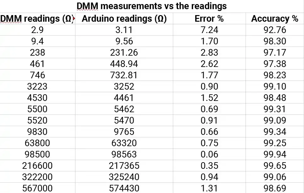
To calculate the accuracy, we measured the output of DMM and Arduino_ohmmeter. The results are as follows:
NOTE: The multimeter used is FLUKE 17B+. On its official website, it mentions an accuracy of 1%.